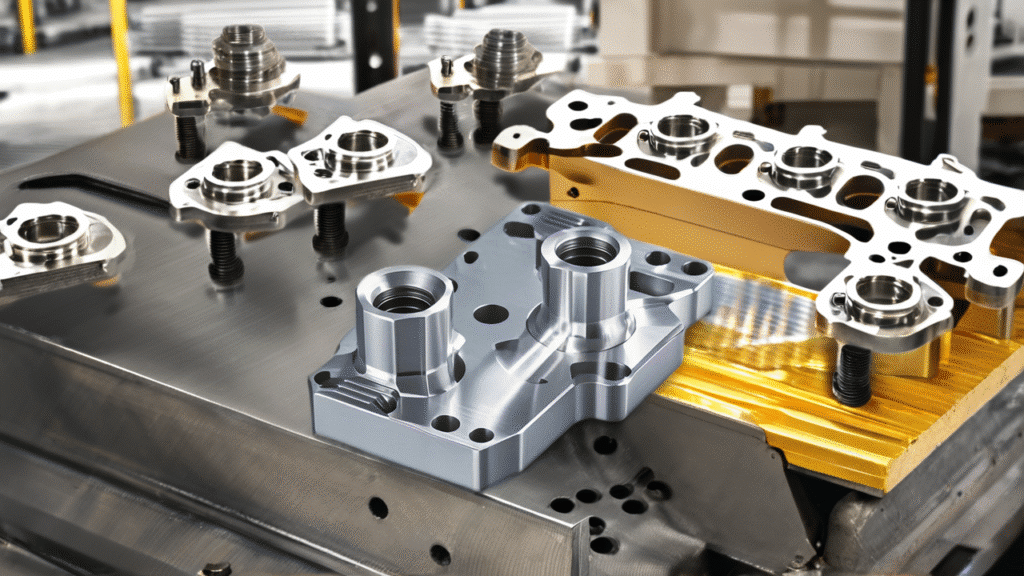
The first step to efficient CNC machining of die casting parts is at the design stage where geometry, datum strategy, and machining allowances are used to establish whether secondary machining is a controlled process or a repeat source of variation. OEM still assumes that die casting and CNC machining are distinct processes, with the latter merely able to correct any problems the former causes. Practically, most CNC problems arise due to poor decision making in upstream design: tool deflection will result due to uneven removal of stock, setup variation will result due to unstable datums, and breakthrough will inevitably result due to poor allowance choices.
CNC machining in parts in CNC parts Die casting facilitates consistent secondary operations and predictable tolerances and scalable manufacture. In the cases where geometry allows repeatable fixturing, repeatable allowances, there are consistent tool engagements and consistent process realities to functional requirements and reduced scrap, cycle times, and total cost all along the chain, first article, to high-volume production.
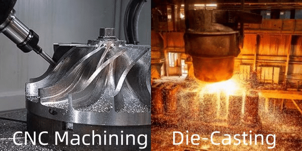
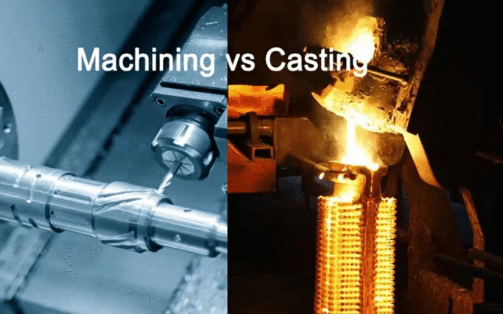
Why CNC Machining Efficiency Starts at the Die Casting Design Stage
Unless the machine tool is introduced prematurely, the basis of creating a CNC machine-friendly process is established long before the part is placed into the machine. Geometry Die casting directly determines tool access and clamping stability as well as material removal behavior of subsequent operations. A component having deep pockets or unsupported thin walls may require complex layering or two or more arrangements, and intermittent wall sections may provide an uneven stress release and distortion following casting.
The early design correspondence among the castings and machining will result in a radically lower level of secondary complexity. Placing features so that they do not interfere with the parting lines, or ejector pins, and stock placement in a way that makes machining predictable will be easier. The connection is simple, casting design intent can be and will be either in favor of machining repeatability or it can sabotage it by introducing inherent variability.
It is this combined model that is of particular use to projects that need CNC machining services whereby we can initially be able to test our designs against the known constraints of real processes.
Key Design Features That Influence CNC Machining Performance
Some of the structural components in a die casting possess disproportionate power on its capacity to be machined effectively and reliably in the downstream. A summary of the most critical and their effect is presented in the table below along with the common pitfalls.
| Design Feature | Impact on CNC Machining | Common Design Mistake |
| Wall thickness consistency | Enhances the stability of the tool and minimizes vibration. | Thick deposits that deposit locally resulting in irregular removal of stock. |
| Boss and rib placement | Less chatter and enhances fixturing. | Features that are not supported or asymmetrical placements resulting in flex. |
| Fillet and corner radii | Enhances the life of the tool and eliminates stress risers. | Straight edges increasing wear or breakout. |
| Draft angles and parting line placement | Ensures clean stock distribution and access | Insufficient draft trapping material or forcing awkward tool paths |
| Cored holes and features | Minimizes material to remove and preserves integrity | Overly deep cores creating thin walls prone to distortion |
The consistency of wall thickness is a special consideration since the variability of it has a direct impact on the heat dispersion during the casting process and the stress distribution in the future. Differential shrinkage as a result of morphometric thick-to-thin transitions becomes apparent as warping or un-uniform flatness-issues that CNC must seek to eliminate. This is reduced by keeping walls constant (usually 2-4mm in the case of aluminum, again depending on the size of the part to be held).
Locating points can also be natural such as bosses and ribs which can be placed symmetrically and attached to larger cross-sections to make the part stiffer than much of the material, reducing vibration in milling or drilling. Misalignment will tend to create undue clamping pressure which will cause deformation.
At least 1 inch or 2 mm fillets on internal corners inhibit the breakage of the component of tool tips and enable tool cuts to flow more smoothly. Sharp edges put a concentration of force, tearing cutters quicker, particularly on high volume dockets.
Fixture and Workholding Considerations During Design
The geometry of the part is a major factor in determining the ease and repeatability of the part in the CNC operations. Large flat datum surfaces of the designs provide easy 3-2-1 fixturing across the critical features where irregular/curved exteriors require bespoke soft jaws or modular clamps, which increases setup time and variability.
The problem is exacerbated by inconsistent surfaces of the references within a batch (as a result of casting warp or ejector marks) and operators have to record each part separately or face the chance of misplacement. Considerable design effort can eliminate this variability, and the addition of fixturing pads, clamping tabs. To learn more about the impact of such decisions, see our guide on CNC fixture design.
Datum Strategy and Its Role in CNC Machining Consistency
Distributable production and intermittent fiddling is divided by a strong datuma plan. Primary locating points of machining should preferably be functional datums (datum related to assembly interfaces or performance), and inspection datums make sure it is in correspondence with real-world activity.
Tolerance stack-up increases rapidly when datums are unstable, e.g. mounted upon as-cast surfaces which are subject to flash, sink or other slight warp. Every arrangement sets in differing conditions and downstream characteristics move off. Good practice is to identify steady accessible planes or points (often machined pads or bosses) which will confine all six degrees of freedom at the earliest stages and then to establish the process around them..
Our detailed discussion on datum selection in CNC machining is a very detailed discussion and how to synchronize those decisions with the casting characteristics and with the final application.
Machining Allowance Design for Stable Secondary Operations
Machining allowance is not an enigma to be guessed at, but rather a conscious design factor in machine usage, the engagement of tools, the amount of heat they generate and the ultimate surface integrity. Constant controlled allowance encourages a consistent state of cutting; too large a stock results in roughing cuts that are heavy and distortive, and too small may result in the revelation of porosity or a poor clean-up operation.
| Allowance Strategy | CNC Outcome |
| Regulated uniform allowance. | A predictable machining, constant tool loading. |
| Excessive allowance | Increased tool wear, increased heat, may be distorted. |
| Insufficient allowance | Surface breakthrough, exposed defects, scrap |
| Variable allowance by feature | Targeted cleanup where needed, material savings |
In the case of die castings made of aluminum, the allowances are between 0.5 and 1.5 mm according to tolerance requirements and feature dimensions- smaller in the more sensitive parts and lighter in the less sensitive parts. The trick here is uniformity between symmetric features in order to prevent skewed forces of removal.
Learn more in our article about machining allowance design for die casting parts.
Designing for Production Consistency in High-Volume CNC Machining
When it comes to mass production, repeatability beats the one time accuracy. A design which is stable in thousands of shots allows the use of automated loading, constant cycle time, and SPC monitoring- whereas a design that changes would require constant operator control.
Semi-automated or fully automated CNC lines are made possible by geometry that does not easily deform (symmetric sections, balanced ribs), datums that can be counted on across batch-to-batch, and geometry that is easily checkable (placement of 3D features relative to each other). Here early co-operation will pay off: checking plans by test of production moulding and machining will warn off drift when the tooling is hardened.
To achieve this degree of stability in strategies, check our article on improving production consistency in high-volume orders.
Common Design Mistakes That Reduce CNC Machining Efficiency
Even well versed teams can slip into unresponsive traps of efficiency. Complex geometries – deep undercuts, excessive thickness of walls or features crammed in close to only allow tool access after slow, multi angle machining. Unreliable fixturing of irregular reference surfaces (using as-cast planes without pads) is used. Implicitly designed systems, such as those that expect manual correction or heroic systems, carry concealed costs and risk.
These are not machining failures; they are exogenous risks which accumulate during the process. Most of them are prevented by awareness at the CAD stage, namely fixturability review, stock uniformity review, and datum robustness review.
Conclusion — CNC Machining Efficiency Is a Design Outcome
An efficient CNC machining does not involve correcting bad designs at the end of the machine run but matching die casting part geometry, allowances and datums with machining realities during its early phases. In cases where engineers consider secondary operations as part of the manufacturing chain and not as a cleaning up level, this leads to predictability of the outcome, reduction in the number of iterations and scaled in case of more successful results.
The most success is achieved with consideration of early coordination between the design and manufacturing teams which we have found to work many times in the automotive bracket, electronic housings, and as well in any other type of high volume application.