The dimensional accuracy of zinc die casting should never be assumed based on the drawings, on the basis of visual checks, or with respect to first-article sample phenomena only. Most OEM teams continue to use manual gauging, optical comparators or even go/no-go fixtures to do their routine checks but in situations where geometric complexity grows or tolerances below ±0.05 mm are required, they become inadequate. They are not good at capturing true positional relationships, form errors, and three-dimensional datum-derived features.
A much more widespread and much more expensive myth is that by drawing a part using tight linear and GD&T callouts, one will automatically be guaranteed that parts will conform of thousands of shots (or even millions of shots). As a matter of fact, it is only a consistent, working process that was tested many times and confirmed by the CMM data that could provide such a result. Drawings determine intent; CMM results indicate the presence of intent across all tooling, thermal control, injection parameters and alloy behavior.
For OEMs sourcing professional zinc die casting services in China, CMM reports is important during supplier audits, submit a PPAP repayment, and, SDC, during the continuous quality control.
What Is CMM Measurement and Why It Matters in Zinc Die Casting
Coordinate Measuring Machines (CMM) are used as the reference in confirming intricate 3D geometry of zinc die castings due to the fact that the devices supply traceable and high-resolution information in controlled coordinate framework.
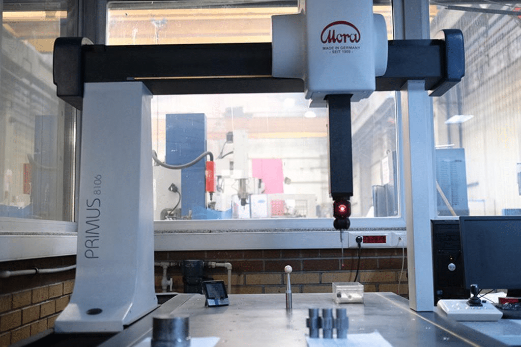
A CMM is a device that requires discrete points or continuous paths upon the surface of the part to measure with precision via a precision probe, and recreates features in reference to fixed datums mathematically. Contemporary bridge-type or gantry CMMs have volumetric accuracy of down to 1.530 -1/350 (ISO 10360), which is good enough to probe the extremely narrow linear tolerances that zinc frequently possesses (±0.0015 in/in or better in small features).
This degree of verification is more in demand by Zinc die casting than many people would suggest. Thin walls (as small as 0.4 mm) and finband or intricate features are possible due to low shrinkage (under 0.6 0.7) and great fluidity, though the same properties enable parts, with regard to time, to be sensitive to small differences in die temperature, wear of the ejector pin, or flash that produces distortion of features important to the part.
Tactile vs Scanning vs Optical CMM Approaches
- Tactile probing – The best at form and position tolerance (true position, flatness, perpendicularity) on rigid zinc components is single-point contact. It does not get surface finish artifacts, but is slower.
- Scanning (continuous-path tactile) – Thousands of points are measured rapidly, and this method is best used with profile tolerances, thin-wall bow, or warpage.
- Optical/laser scanning Non-contact, free-form shapes and delicate features are faster, but with worse absolute accuracy (usually 10-30 μm) is auxiliary instead of primary to tight GD&T in zinc.
| Measurement Method | Capability | Limitation in Zinc Die Casting |
| Tactile (single point) | Highest absolute accuracy (~1–3 µm) | Slow for dense point clouds; risk of probe force on thin features |
| Scanning (tactile) | Excellent for form & profile; dense data | Requires clean surfaces; slower than optical |
| Optical / laser scanning | Fast full-field capture; non-contact | Lower precision; sensitive to surface reflectivity & texture typical in as-cast zinc |
Dimensional Accuracy vs Dimensional Consistency
Dimensional accuracy captures a point: Does this one part print at time T? It is the dimensional consistency which is required of production – can the process be repeatable that accuracy across shifts, tool life, and seasonal temperature changes?
A CMM report with everything on a single report would make you know virtually nothing about long term risk. More important is control of important characteristics greater than 30-100 successive shots (or more) of a process, capability indices (Cp/Cpk =1.67 or higher of critical features) and trend analysis to determine whether shift in the mean or a rise in variation is taking place.
Consistency performance is generally more effective than one-time accuracy in zinc die casting since the alloy exhibits predictable shrinkage and little remaining stress levels permit modest process windows, assuming die temperature, shot velocity and lubrication are held constant.
| Metric | One-Time Result Meaning | Process Capability Insight |
| Single measurement | Part conforms / nonconforms at that moment | Limited — no information on variation or drift |
| Cp (potential capability) | How well centered process could perform | Indicates inherent process spread vs tolerance |
| Cpk (actual capability) | Accounts for centering & variation | True predictor of long-term nonconformance risk |
| Trend / control chart | Shows stability over time | Detects special causes (tool wear, temp shift) early |
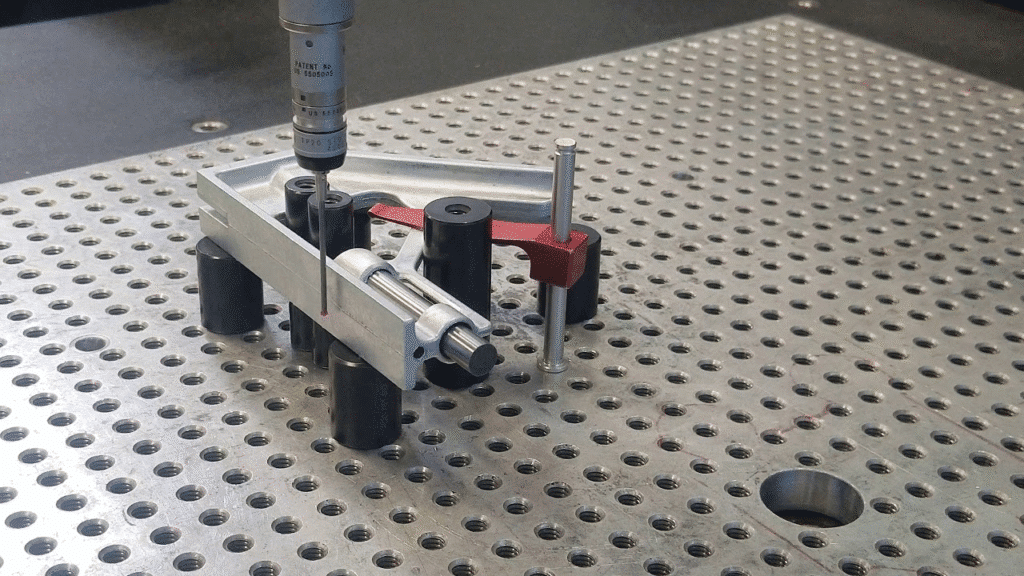
How CMM Verifies Critical Zinc Die Casting Features
The proper CMM programming begins with alignment of the data reference frame that corresponds to functional meaning – typically primary dataum on a large mounting surface, secondary on a bore or an edge, tertiary on a clocking feature.
Some of the common high risks in zinc parts are:
- Real location of holes – Typically ±0.1 and 0.2 mm MMC; CMM probe must touch at mid-plane or best-fit algorithm to eliminate cosine error.
- Flatness of sealing/ gasket faces Zinc may bow away due to uneven cooling; scanning curves can illustrate the presence of peaks and valleys.
- thin-wall thickness variation – In electronics cases; several probe points or scan to map distribution are necessary.
- Basic information of intricate surfaces — Decorative or practical radii; scanning CMMs are effective here.
| Feature Type | Measurement Focus | Risk if Unverified |
| Datum features (planes, bores) | Alignment repeatability | Misalignment cascades to all dependent tolerances |
| Hole / boss true position | Position at MMC / RFS | Assembly interference or loose fits |
| Flatness / straightness | Form deviation across surface | Leak paths in housings; uneven load distribution |
| Thin walls / ribs | Local thickness & bow | Structural weakness or warpage in secondary operations |
Relationship Between Design Intent and CMM Strategy
CMM programming should not be led by the GD&T call outs but the other way around. Over-dimensioning (making all the features very extreme) prioritizes the inspection time and expenditure that are not needed and covers up priorities regarding functions. Realistic process capability is enabled by functional dimensioning which focuses the tight controls on mating interfaces and datum features.
A well drawn drawing indicates datums that represent assembly function and then only implement position, profile, or runout where variation has direct affect on fit, function, or perceived quality. CMM strategy is then used: probe sequences are ranked in terms of those controls using constructed features and composite tolerances where relevant.
In our design guidelines of zinc die casting, zinc die casting design guidelines for practical GD&T application in zinc parts.
Using CMM Data to Compare Manufacturing Processes
The low shrinkage and high fluidity of zinc provides zinc with a distinct advantage in as-cast dimensional repeatability over aluminum (higher of the order of 1.3% shrinkage, greater warpage potential). The data of production runs analyzed by CMM reveals higher Cpk values of zinc on such features as the position of a hole and flatness with no secondary machining.
Zinc die casting is likely to provide the best combination of tolerance, speed and cost particularly when manufacturing mid-volume functional pieces, in comparison with CNC machining (removal yields tolerance up to ±0.01 mm, but cost per part increases with setup volume) or metal injection molding (MIM, very small parts only, and slower cycle times).
For deeper reading:
How CMM Measurement Supports Downstream Assembly and Packaging
Stable dimensional performance literally translates into reliable fit and performance in assembling. Where CMM data portrays precise capability on mating features (bore diameters, boss heights, locating pins), OEMs can minimize shimming, rectifying assembly, or shredding.
Packaging also uses repeatable geometry. Elements that are stable and exhibited a low bow and flatness can be stacked closer together or lighter protective inserts that are not prone to deformation during transit are used.
Learn more about strategies in custom packaging for zinc die casting parts.
Common OEM Misconceptions About CMM Measurement
Stereotypical OEM Misconceptions regarding CMM Measurement.
- Most of the OEM engineers continue to have the old fashioned ideas on what CMM data entails.
- When the CMM report is green, the process can operate within an infinite period. Fact: a single good report does not count; a test one has to achieve with time and subsequent changes in the processes.
- The more the measurement points the better the quality. Reality: Extra points are a waste of time when they are not aimed at functional features. Smart programming is concerned with risk areas.
- Final inspection CMM is adequate to control quality. Reality: With end-of-line checks only, one cannot get upstream drift. First-off or in-process CMM monitoring is much more effective in terms of prevention.
Conclusion — CMM Measures Capability, Not Promises
Measurement machineres do not produce accuracy, they measure how well die casting, starting with tool design, shot parameters and control of the alloy can provide it repeatably. The true worth resides in the application of CMM trends, capability statistics, and datum-aligned feature data to qualify the suppliers, optimize the tooling and attain long term stability.
To OEMs, the art of CMM evidence which requires a high level of discipline isolates good sources of zinc die casting and those which are dependent on luck or first article miracles.