There is no single best manufacturing process that fits and could work all around – process choice will always depend on the individual part geometry, material needs, batch of production, tolerance needs, and lifecycle cost objectives.
At low volumes, where CNC machining may be considered of minimal risk, many OEM engineers may fall back on metals injection molding (MIM) with its perceived simplicity when they observe high complexity, but zinc alloy die casting may often be a more balanced and cost-effective P2P option at much larger scales once volumes leaving prototypes or low thousands. The trick is that one should see the distinct decision boundaries that define the point where zinc die casting would become not only possible but also optimal.
Zinc alloy die cast is the manufacturing method of choice when the complexity of parts, dimensional stability, and volume of manufacturing part are more important than the flexibility of machining and the density limits of MIM.
To get more specific applications of high precision, see our guide to precision zinc die casting parts manufacturing.
Comparing Zinc Die Casting, CNC Machining, and MIM at a System Level
The basic differences between these three processes, in their core, construct the metal parts with entirely different mechanisms, which directly predetermines their strengths, weaknesses, and ideal situations to be used.
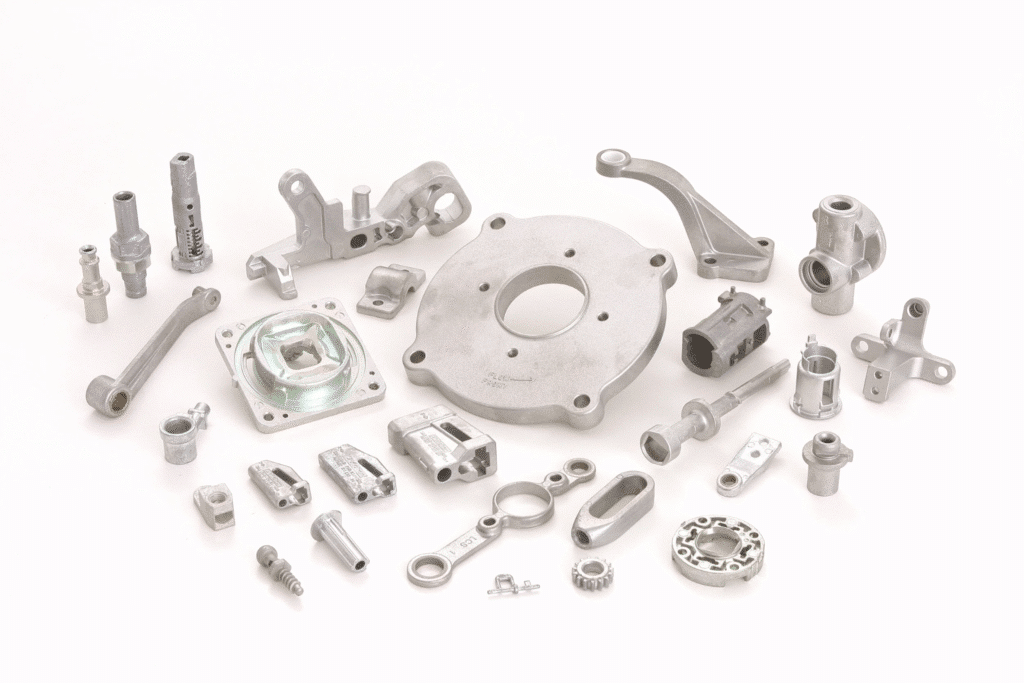
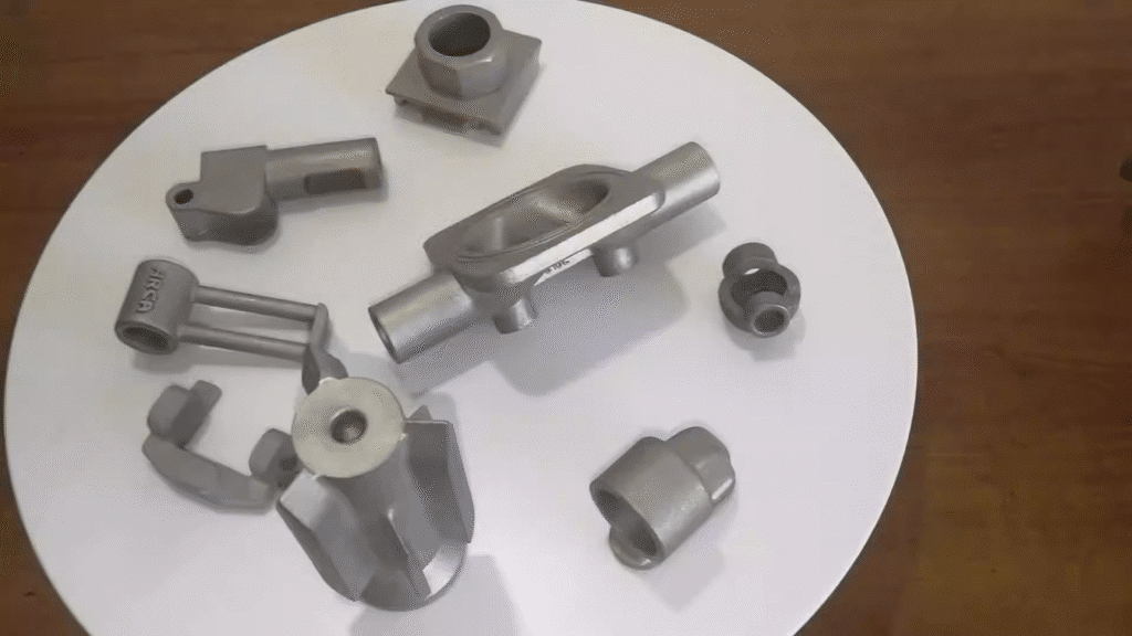
Zinc die casting puts high pressure on the molten zinc alloy (usually Zamak 3 or 5) in a reusable tool made of steel and then enables the under pressure solidification of net-shaped high density parts of around 95% repeatability when the tool is proved successful.
CNC machining begins with a solid billet (typically either extruded or forged stock) and removes material through cutting tools, with an unparalleled design flexibility that scales up to large amounts of waste and huge cycle-time penalties.
MIM is the way to combine fine metal powders with binders, inject the feedstock into a mold, debind, and sinters the so-called green part to almost full density, which is very helpful with geometries of higher melting alloys but also leads to the variability of shrinkage.
| Process | Strengths | Limitations | Best-Fit Applications |
| Zinc Die Casting | Fast cycles, thin walls, excellent as-cast finish, stable geometry at volume | Upfront tooling cost, limited to low-melt alloys (zinc primary) | Medium-high volume functional + cosmetic parts, thin-wall housings, brackets |
| CNC Machining | Extreme precision, easy iterations, any material | High per-part cost and waste at volume, slow for complex shapes | Prototypes, low-volume, ultra-tight features requiring post-processing |
| MIM | Very complex geometries, wide material range (steels, exotics), near-net shape | Multi-step process with shrinkage (15–18%), lower density possible, small parts only | Small, intricate components in high-performance alloys, medical/electronics |
Dimensional Stability and Tolerance Control
It is also feasible to note that with most production-based scenarios, zinc alloy die casting provides excellent long-term dimensional stability as opposed to the substitutes.
Since the molten zinc is solidified under pressure with negligible shrinkage (around 0.4-0.7percent), machined parts are prone to thermal expansion, tool life, and variation in fixturing which is more difficult to stabilize over tool life as compared to constant offsets and checks, because it becomes difficult to repeat without the constant use of offsets and checks. Sintering isotropically and anisotropically shrinks MIM parts, and may shift critical dimensions unless tightly-controlled even in the case of lot-to-lot part variation is commonly worse than zinc die casting.
To understand further on why zinc is the most ideal component in this case, read about the dimensional stability of zinc alloy die casting.
Thin-Wall Capability and Complex Geometry
Zinc alloy is used where designs require thinness of walls with structural integrity.
The low melting point (c. 380420C) and great fluidity of zinc enables walls as thin as 0.3-0.5 mm to flow and fill reasonably large surfaces in practice but still good mechanical properties and surface characteristics. The thin walls cannot be machined efficiently and safely CNC machining thin walls is inefficient and often prone to vibration, deflection and chatter, compelling thicker material into use or more setups to incur exorbitant costs. MIM is able to reach extremely fine features (down to around 0.15 -0.5 mm), although density limits and removal of binder restrictions make it prone to warping or non-sintering in large thin areas.
Read guidelines that can be put to practice in our article on the advantages of thin-wall zinc die casting.
Tolerance Expectations Across Processes
Value Practical achievable tolerances differ to a large degree with the type of features and size as well as maturity of the processes.
Zinc die-casting is used routinely with about -.05 -1 mm control on linear feature size (tighter on smaller features), and repeats well, due to pressure-assisted filling. CNC machining is found capable of doing ±0.005- 0.025 mm (better with high-quality systems) but at a very high premium to the price per part when quantities are high. MIM normally obtains a variation of dimension of between +-0.3 to +-0.5% (in many occasions +-0.05 to +-0.15 mm on little portions), whereas sintering fluctuation calls an excessively large margin in its design or, typical tolerances for zinc die casting parts and control strategies.
Defect Risk and Process Reliability
Individual processes have specific defect risks affecting the reliability in the production scale.
The main risks of zinc die casting, porosity, flash, and cold shuts, can be reduced to almost zero by die design, gating, venting and process monitoring; current hot-chamber machines and automation ensure a low scrap rate (<1 2 typical). The defects at CNC machining (tool marks, burrs, dimensional drift) are largely operator- or set-up dependent and more likely to accumulate as a result of fatigue during the long runs. The greatest difficulties MIM faces are related to the debinding/sintering (cracks, distortion and incomplete densification) process, which may be more difficult to predict and control without a significant amount of validation.
Common issues and prevention tactics are covered in our post on the causes of zinc die casting defects.
Quality Inspection and Process Control Requirements
Strong internal inspection capacity becomes indispensable as uniform production is maintained irrespective of the process again however, inspection workload varies.
Zinc die casting has the advantage of having simple checks: CMM of dimensions, X-ray of internal porosity, spectrometer of alloy composition, and tensile of mechanicals. Since defects are near-surface or surface dominant, defects are detected at a very young stage by automated vision and pressure test. Machining involves probing in-process and checking tools frequently in order to maintain tolerances. Shrinkage variability increases MIM sintering-furnace monitoring require and more post-process validation.
In-house capabilities drive reliability—learn how quality inspection in zinc die casting manufacturing reduces variation, and why X-ray testing of zinc die casting parts catches hidden issues.
Cost Structure and Volume Break-Even Points
The lowest initial tooling cost (usually 10000-80000+ depending on complexity) is in zinc die casting, and very low-scale part costs due to 1030 second cycles and low material wastage. The tooling in CNC machining is close to zero, however labor/machine time and scrap rate is high. The MIM tooling is in between, although the cost of the unit remains higher up to very high volumes through longer cycles and secondary operations.
| Cost Factor | Machining | MIM | Zinc Die Casting | Decision Insight |
| Tooling Cost | Very low / none | Medium–high | High | Amortized fastest in zinc at >10k–50k units/year |
| Unit Cost at Low Volume | Lowest | Medium | Highest | Stick with machining for <5k units |
| Unit Cost at High Volume | Highest | Medium | Lowest | Zinc wins >20k–100k+ units |
| Material Utilization | Poor (30–70% waste) | Good | Excellent (>95%) | Zinc minimizes raw material spend |
| Secondary Operations | Often required | Frequently required | Minimal | Reduces total landed cost in zinc |
Clear Scenarios Where Zinc Die Casting Is the Better Choice
Based on decades of experience in favor of OEM programs, some trends can be outlined in which the use of zinc alloy die casting has always been higher than the alternatives.
- High to medium volume production (20,000-500,000 or more yearly) the amortization of machinery is recovered in a short time.
- Components with high tolerance (0.5 -1.5 mm) as well as structural ribs / bosses – common to automobile brackets, electronic enclosures, lighting fittings and cosmetic components.
- Designs requiring functional (strength, EMI shielding, thermal conductivity) and cosmetic surface (plating-ready finish) and not heavy secondary finishing.
- Components are already produced as assemblies (often as an accessory or sub-unit called component parts), which minimize the number of parts required and the amount of labor needed in assembly.
In such scenarios, zinc die casting provides a predictable quality, it has a shorter lead-time with the approval of the tooling and also is cost effective as compared to forcing MIM to density limit geometries or machining everything possible on a billet.
Conclusion — Process Selection Is a Strategic Engineering Decision
Finally, the decision between zinc alloy die casting, CNC machining and MIM will always be about the declaration of never stating which process is the best, the key to it, is the relationship between the process physics and the part requirements like performance, shape, risk life cycle, and cost of ownership.
There are too many programs that stem into machining when they are not feeling comfortable or pushes MIM because of the perceived complexity benefit only to later find out that zinc die casting would have offered more stability, nicer thinner walls and reduced the scaled costs significantly. The wisest step is to start early, data-driven comparison prototype the most flexible process, and reassess it when the design and the forecast converge.
Call according to actual application behavior as opposed to expectations. The appropriate process minimizes downstream surprises and cushions program margins.